ODAX EDA Standard Sensor Kit
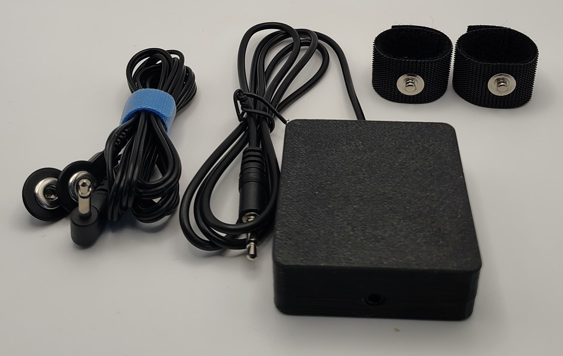
EDA/GSR kit with an enclosed ODAX EDA Standard Board, two maker-grade black Ag/AgCl contact straps, snap leads, and a 3.5 mm TRS analog interface.
Overview
The ODAX EDA Standard Sensor Kit brings together an enclosed analog sensor, finger contact straps, and cables for electrodermal activity (EDA) and galvanic skin response (GSR) experiments.
Built around the ODAX EDA Standard Board, the kit includes a black enclosure, two ODAX EDA Contact Straps - Maker Grade - Black, matching snap leads, and a 3.5 mm TRS cable for power, ground, and analog output.
SKU: ODAX-EDA-SK1-100-BLK-R1
It follows the enclosed-sensor approach of the ODAX EDA Research Sensor Kit - Black, using the Standard Board's maker-grade analog circuit and MT1 contact straps. The sensor supplies an analog voltage for your own microcontroller or acquisition system to sample, log, and process.
The kit is intended for prototyping, evaluation, relative EDA/GSR trend measurement, biofeedback experiments, and embedded development. It is not a medical device and is not intended for diagnosis, monitoring, treatment, or safety-critical use.
Kit Contents
- Enclosed ODAX EDA Standard Board in a black enclosure. Board SKU / MPN:
ODAX-EDA-SB1-100-BLK-R1 - Two ODAX EDA Contact Straps - Maker Grade - Black. Strap SKU:
ODAX-EDA-MT1-100-BLK-R1 - Black electrode lead set with two snap connectors and a 3.5 mm TS plug
- Black 3.5 mm TRS sensor cable for analog output, power, and ground
Product Photos
Enclosed Standard sensor with contact straps and cables
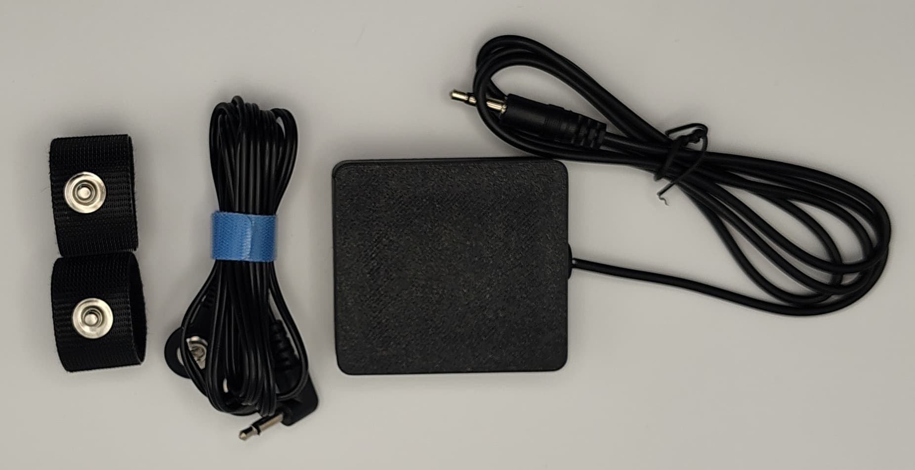
Alternate view with the straps' skin-contact surfaces visible
The Components Inside the Kit
ODAX EDA Standard Board
The Standard Board uses the same analog circuit and electrical routing as the ODAX EDA Maker board in a 35 × 31 mm PCB format. Its transimpedance-amplifier front end applies a low-voltage electrode bias, measures the skin-current response, and provides a ground-referenced analog output. Higher skin conductance produces higher output voltage.
- Maker-grade analog EDA/GSR signal conditioning
- Recommended 3 V to 5 V battery-powered operation
- Approximately DC to 6 Hz useful signal bandwidth for slow EDA/GSR signals
- Analog output for a high-impedance microcontroller ADC input
View the ODAX EDA Standard Board for full electrical specifications and board details.
Maker-Grade Black Contact Straps
The two maker-grade black contact straps hold Ag/AgCl electrode surfaces against the fingers with reusable hook-and-loop closures. Each strap has a nominal length of 100 mm and a 3.9 mm snap stud interface for the electrode leads.
Component Datasheets
Refer to the component datasheets for board specifications and contact-strap details.
Simple 3.5 mm Analog Interface
The sensor cable carries the three connections needed by the host acquisition system on a 3.5 mm TRS plug:
| TRS contact | Signal | Function |
|---|---|---|
| Tip | VOUT / OUT | Ground-referenced analog EDA/GSR output; connect to a high-impedance ADC input |
| Ring | VIN / PWR | 3.0–5.0 V DC input power |
| Sleeve | GND | Common ground shared with the ADC system |
The Standard Board labels its power and output connections PWR and OUT. These correspond to VIN and VOUT in the Maker board documentation.
The connector carries sensor power and signal, even though it has the familiar audio-plug shape. Do not connect it to headphones or audio equipment. Keep the output within the receiving ADC's permitted input range.
Why Choose the Standard Sensor Kit
- Combines the Standard Board, enclosure, two maker-grade straps, and cables in one kit
- Keeps the bare board enclosed during experiments and prototyping
- Provides a simple analog interface for your own sampling, logging, and signal-processing firmware
- Supports relative EDA/GSR trend tracking, event detection, and biofeedback experiments
- Links directly to the board and electrode documentation for integration details
Getting Started
- With power off, connect the TRS tip to the host ADC input, ring to the battery-powered 3–5 V supply, and sleeve to common ground.
- Connect the snap electrode lead set to the sensor's electrode input.
- Attach the two snap connectors to the maker-grade contact straps and place the straps on adjacent fingers of the same hand.
- Keep contact pressure comfortable and consistent, and support the cables to reduce movement.
- Apply power, allow the signal to settle, and sample the analog output with a high-impedance ADC input.
Use battery power while the electrodes contact skin. Do not connect the setup to mains-referenced equipment unless the complete system has appropriate isolation designed and verified by a qualified person.
Measurement quality depends on electrode and skin condition, contact pressure, motion, ADC scaling, filtering, and calibration. See the Standard Board product page and maker-grade contact strap product page for further guidance.
Ordering Information
- Product: ODAX EDA Standard Sensor Kit
- SKU / part number: ODAX-EDA-SK1-100-BLK-R1
- Color: Black
- Product family: ODAX EDA Standard Sensor Kit SK1 Series
- Format: Enclosed Standard Board with two maker-grade contact straps, electrode leads, and TRS sensor cable
Contact us for product and ordering inquiries.