ODAX EDA Maker

Compact maker-level electrodermal activity EDA (galvanic skin response GSR) analog sensor board with ground-referenced analog output for microcontroller ADC input.
Overview
The ODAX EDA Maker is a compact analog sensor board for builders who want to work with electrodermal activity EDA (aka. galvanic skin response GSR) without designing the front end from scratch.
It gives you a clean, ground-referenced analog output that can be connected directly to a microcontroller ADC, so you can move quickly from concept to working prototype.
At the board level, it applies a low-voltage electrode bias, measures the resulting skin-current response with a TIA-based analog front end, and produces a slope VOUT signal. As skin resistance changes, the output voltage changes with it, giving developers a straightforward path into firmware, logging, filtering, and event detection workflows.
The module is intended for relative EDA and GSR trend measurement, biofeedback experiments, prototyping, and custom product development. It is not a medical device and is not intended for diagnosis, monitoring, treatment, or safety-critical use.
Why Makers Buy It
- Faster path from concept to working EDA prototype
- Simple
VIN,GND, andVOUTinterface for embedded development - Compact assembled board format that is easy to fit into test rigs and portable builds
- Works with ODAX contact straps and ODAX electrode-lead setups
- Suitable for maker projects, HCI experiments, biometrics, and exploratory biosignal development
What You Can Build
- Rapid EDA and GSR proof-of-concepts
- Biofeedback demos and interactive installations
- Wearable sensing prototypes with external logging or control firmware
- Human-computer interaction and psychophysiology experiments
- Custom embedded systems that need a simple analog biosignal input
Datasheet
Product Photos

Back view
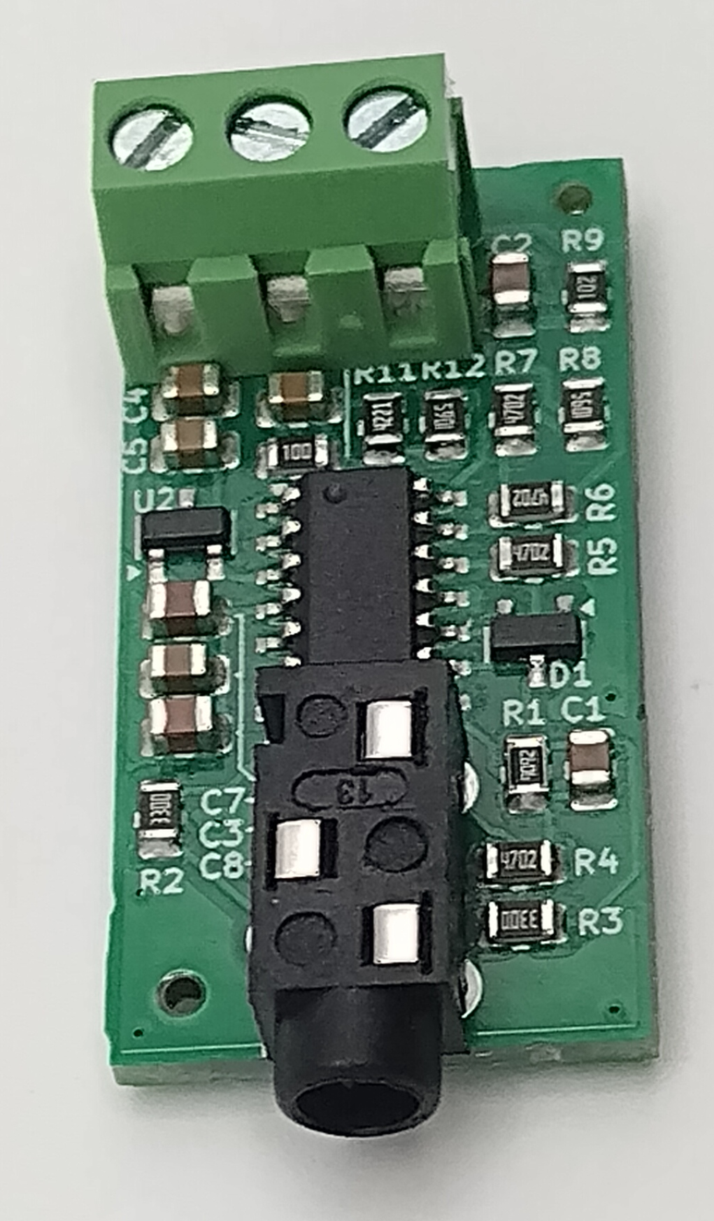
Front view
Key Features
- Compact maker-level EDA and GSR analog sensor board
- TIA-based analog front end with positive-slope voltage output
- Recommended 3 V to 5 V DC supply from a battery-powered system while electrodes contact skin
- 3.5 mm jack interface for two electrode lead contacts
- Suitable for relative trend measurement, event detection, and biofeedback experiments
Built for Prototyping
The board is intentionally simple to integrate. Supply power, connect VOUT to a high-impedance ADC input, attach two electrodes, and start collecting signal data. That makes it a better fit for early-stage development than building a custom analog chain before you know what your application needs.
For teams exploring wearables, psychophysiology, human-computer interaction, or custom biosignal devices, the ODAX EDA Maker provides a practical starting point while still leaving room for your own sampling strategy, filtering, calibration, and application logic.
Applications
- EDA and GSR measurement for prototyping and maker projects
- Psychophysiology, HCI, affective computing, biometrics, and biofeedback experiments
- Wearable sensing prototypes using standard electrode lead sets
- Low-frequency analog bio-signal sensing
Technical Details
Recommended Operating Conditions and Electrical Characteristics
| Parameter | Symbol | Min | Typ | Max | Notes |
|---|---|---|---|---|---|
| Supply voltage, recommended | VIN | 3.0 V | 3.3 V or 5.0 V | 5.0 V | Battery-powered system while electrodes contact skin |
| Supply voltage, tolerated functional range | VIN | 3.0 V | 5.5 V | Not the recommended operating range; verify in the end system | |
| Analog output voltage, representative use | VOUT | 0.1 V | 1.2 V | Resistor-substitution bench observations over a practical range | |
| Useful signal bandwidth | BW | DC | about 6 Hz | Intended for slow EDA and GSR signals | |
| Practical resistor-simulator range | Rskin | about 50 kOhm | about 1 MOhm | Representative range; skin and electrode behavior vary | |
| ADC input impedance | ZADC | 100 kOhm | Higher impedance preferred | ||
| Output response direction | Positive | Higher conductance produces higher VOUT |
User Connections
| Connection | Direction / Contact | Description |
|---|---|---|
VIN | Input | DC supply input. Recommended 3 V to 5 V from a battery-powered system while electrodes contact skin |
GND | Reference | Common ground for the board and the ADC system |
VOUT | Output | Analog EDA/GSR output. Connect to a high-impedance ADC input |
| 3.5 mm jack tip | E+ | Electrode drive contact. Connect to one skin contact strap or electrode |
| 3.5 mm jack sleeve | E- | Measurement return contact. Connect to the second skin contact strap or electrode |
| 3.5 mm jack ring | NC | If a TRS jack or plug is used mechanically, the ring contact is not used by the board |
Mechanical
| Parameter | Nominal | Unit | Notes |
|---|---|---|---|
| PCB length | 33 | mm | Nominal board dimension |
| PCB width | 17 | mm | Nominal board dimension |
| Electrode connector | 3.5 mm jack | Used as TS for two electrode lead contacts | |
| User electrical interface | VIN, GND, VOUT | Three simple user connections |
Getting Started
- Power the board from a battery-powered 3 V to 5 V system.
- Connect
VOUTto a high-impedance ADC input and share commonGND. - Attach two skin-contact electrodes or ODAX EDA contact straps to the 3.5 mm electrode jack.
- Place the contacts on adjacent fingers of the same hand.
- Route the cable to minimize motion and keep contact pressure consistent during measurement.
This setup is intended for relative signal tracking and experimentation. End-system performance depends on electrode condition, skin condition, contact pressure, motion, and calibration choices.