A very simple way to use the ODAX EDA Maker Kit
A step-by-step photo tutorial demo setup of the ODAX EDA Maker Kit.
Introduction
Getting started in EDA (Electrodermal Activity sensing also known as GSR Galvanic Skin Response) is an exciting area of biometrics/biofeedback. The Odax EDA Maker Kit provides the key components for this: Analog sensing board, the electrode leads and skin contacts. Details on the kit can be found by following the button to the product page:
Most usecases will be utilizing a single board computer like Ardruino or a Raspberry Pi, but here a very simple approach will be described for those seeking an quick way to observe Electrodermal activity.
Step 1
Here is an image of all the items needed to follow this simple demo setup.
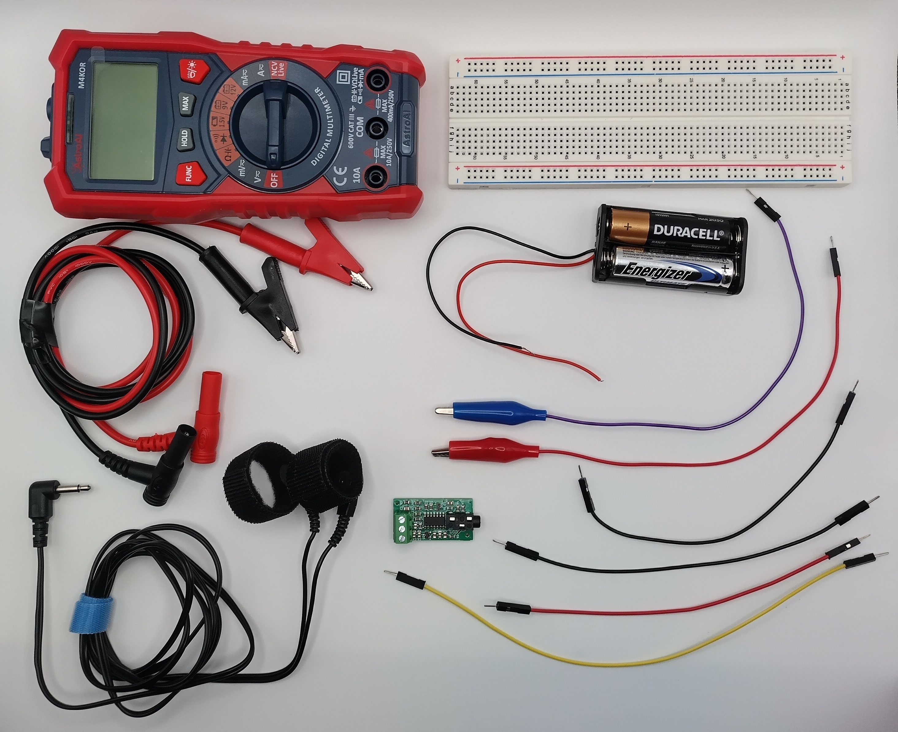
The parts needed to follow the basic EDA sensing tutorial.
The items shown in the image:
- 1 Odax EDA Maker Kit (includes the circuit board, electrode leads, contact straps)
- 1 Voltmeter with alligator contacts (snap contacts)
- 1 Breadboard
- 4 Male-Male jumper wires
- 2 Male jumper wires with alligator clip
- 1 battery holder for 2 AA batteries
- 2 AA batteries
Step 2
Connect the batter supply to the jumper wires so that the positive and negative are inserted into the Breadboard as shown.
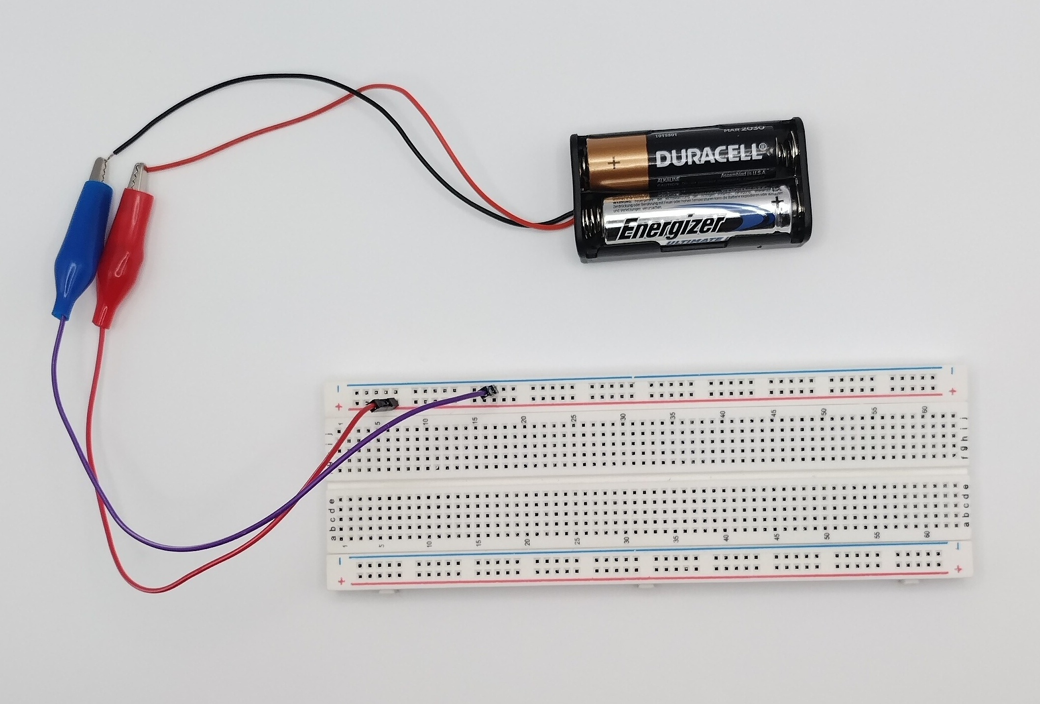
Connecting the battery pack to the breadboard.
Step 3
Connect the 3 Male-Male jumper wires to the EDA board. It is customary to have the red go to the board Vcc, the black to the GND and another color like yellow to the Vout (board sensing output). You can use the terminal block to screw the wires into place.
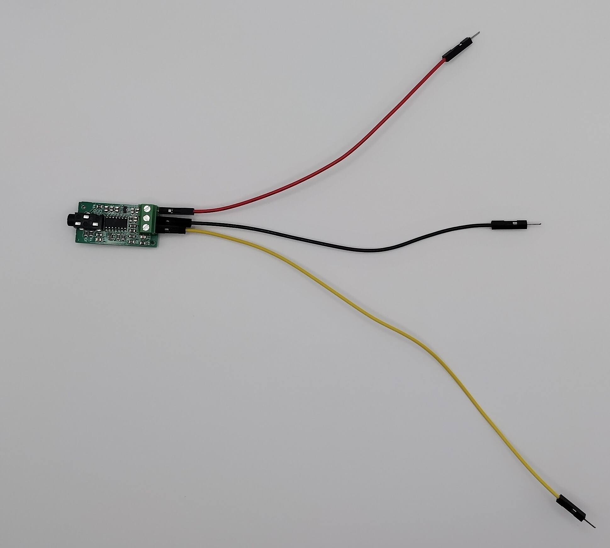
Placing the jumper wires onto the EDA board.
Step 4
Connect the EDA board's Vcc (red) to the breadboard power line (also red). Then connect the jumper wire's GND (black ground) to the negative of the breadboard (here blue rail). Leave the yellow signal Vout free for now.
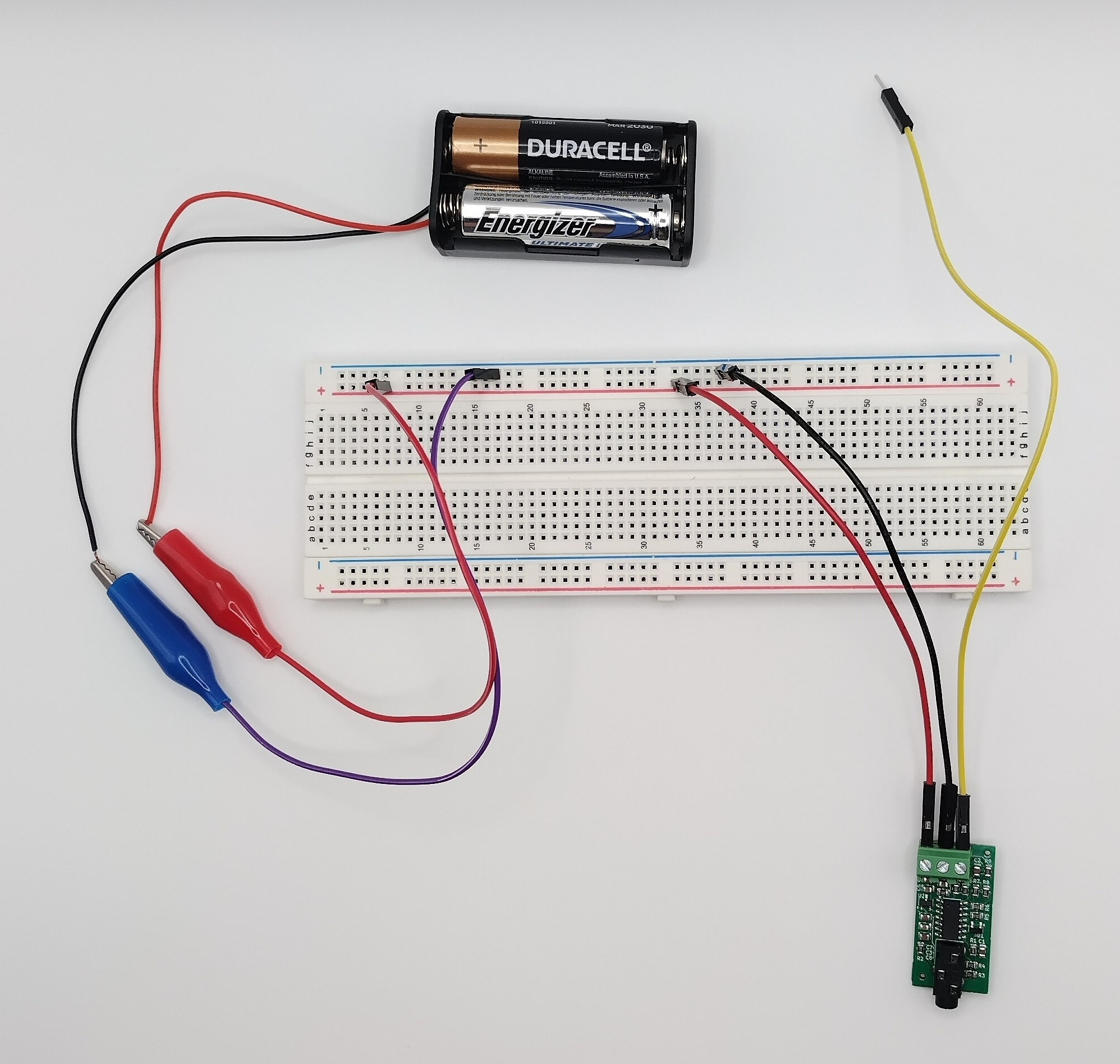
Connecting the baord to the PCB board with power.
Step 5
Turn on the Voltmeter setting it to measure Voltages (V symbol). Connect the Voltmeter black aligator clip to the black jumper wire which will go onto the breadboard ground. Then connect the Voltmeter red clip to the yellow wire coming from the board's Vout (yellow). Lastly connect the electrode leads to the board by inserting the 3.5mm audio jack into the board.
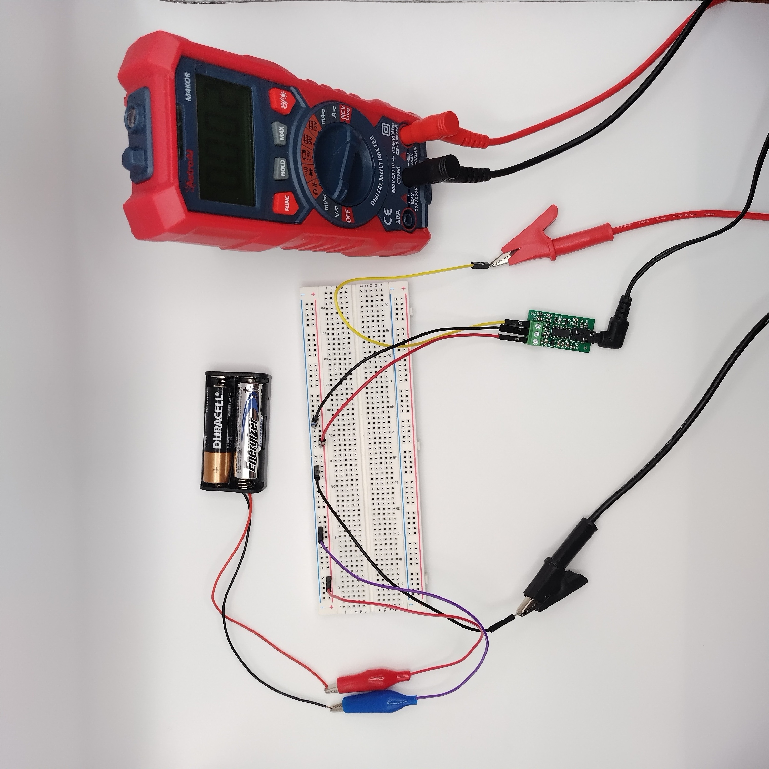
Connecting the Voltmeter to the breadboard and the electrode leads to the circuit.
Step 6
Now you are ready to take your first measurements by placing a strap around your index finger and another around the middle finger. The Voltmeter should now display a voltage.
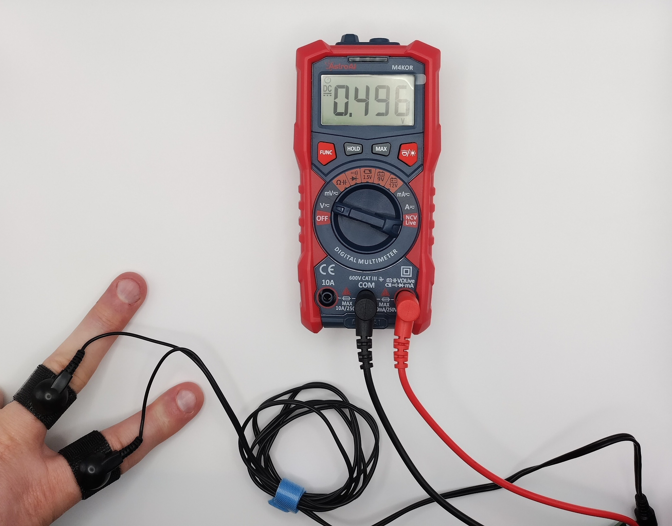
Connecting the contact straps.
Step 7
If the physiological response of the subject has changed then the voltage displayed will change as a result.
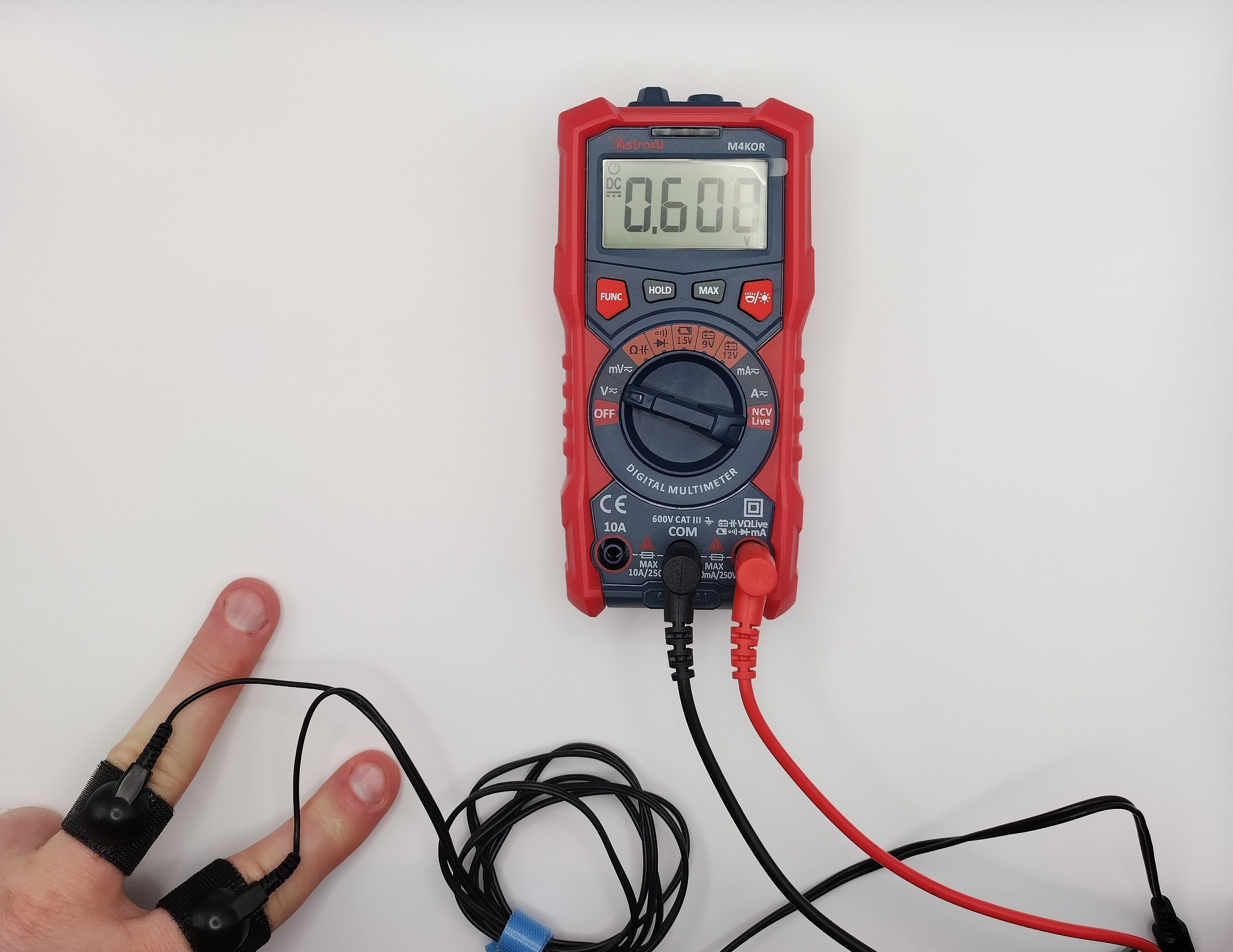
Displays of changed Electrodermal activity.
Ending
This concludes the simple setup demonstration. It is a convenient way to explore the usage of the kit with minimal setup.